
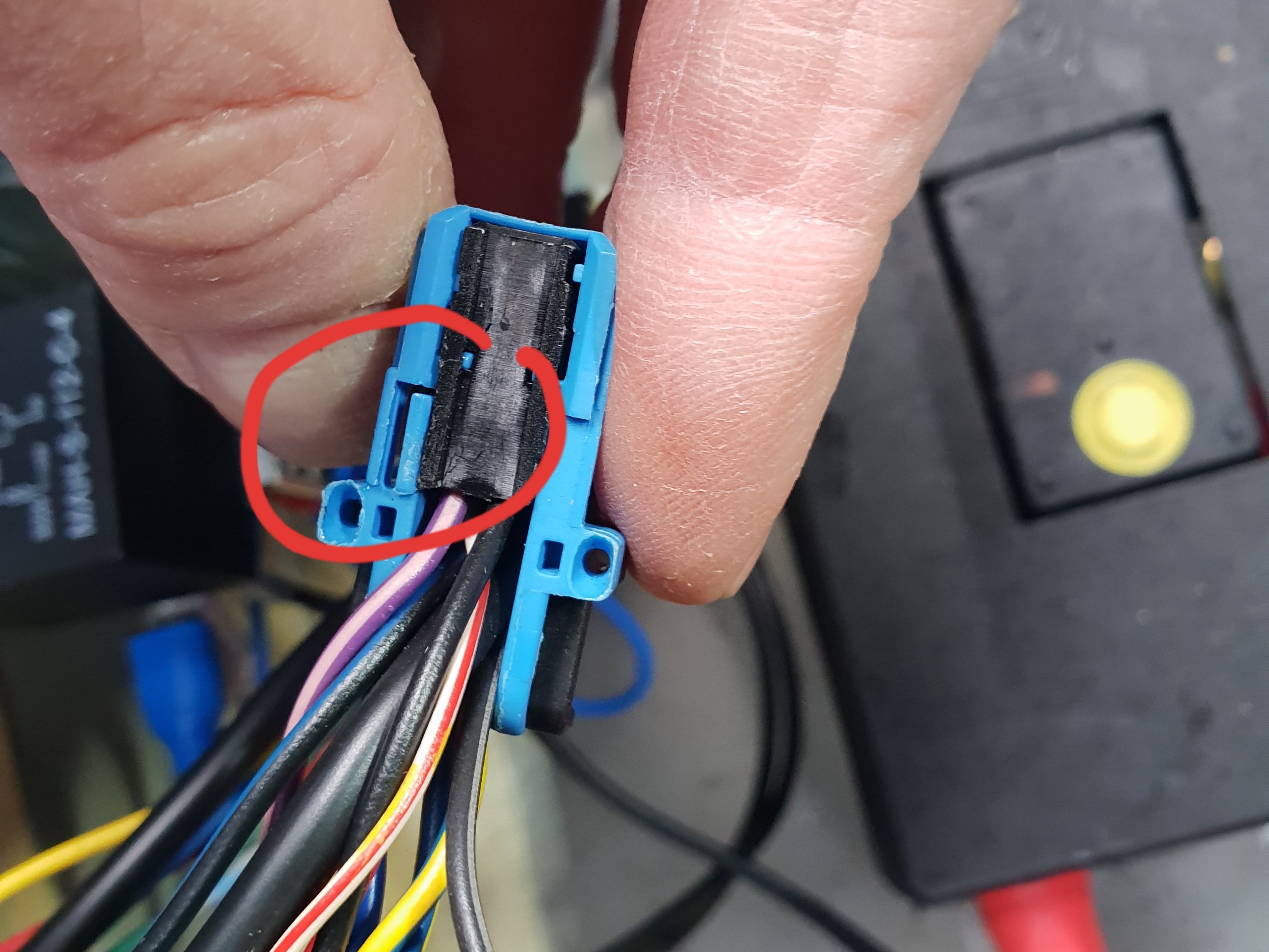
The final stage is adding the new pins into the blue and white plugs. Release the plugs from the tv unit. Then remove the terminal block from the holder – see pic.
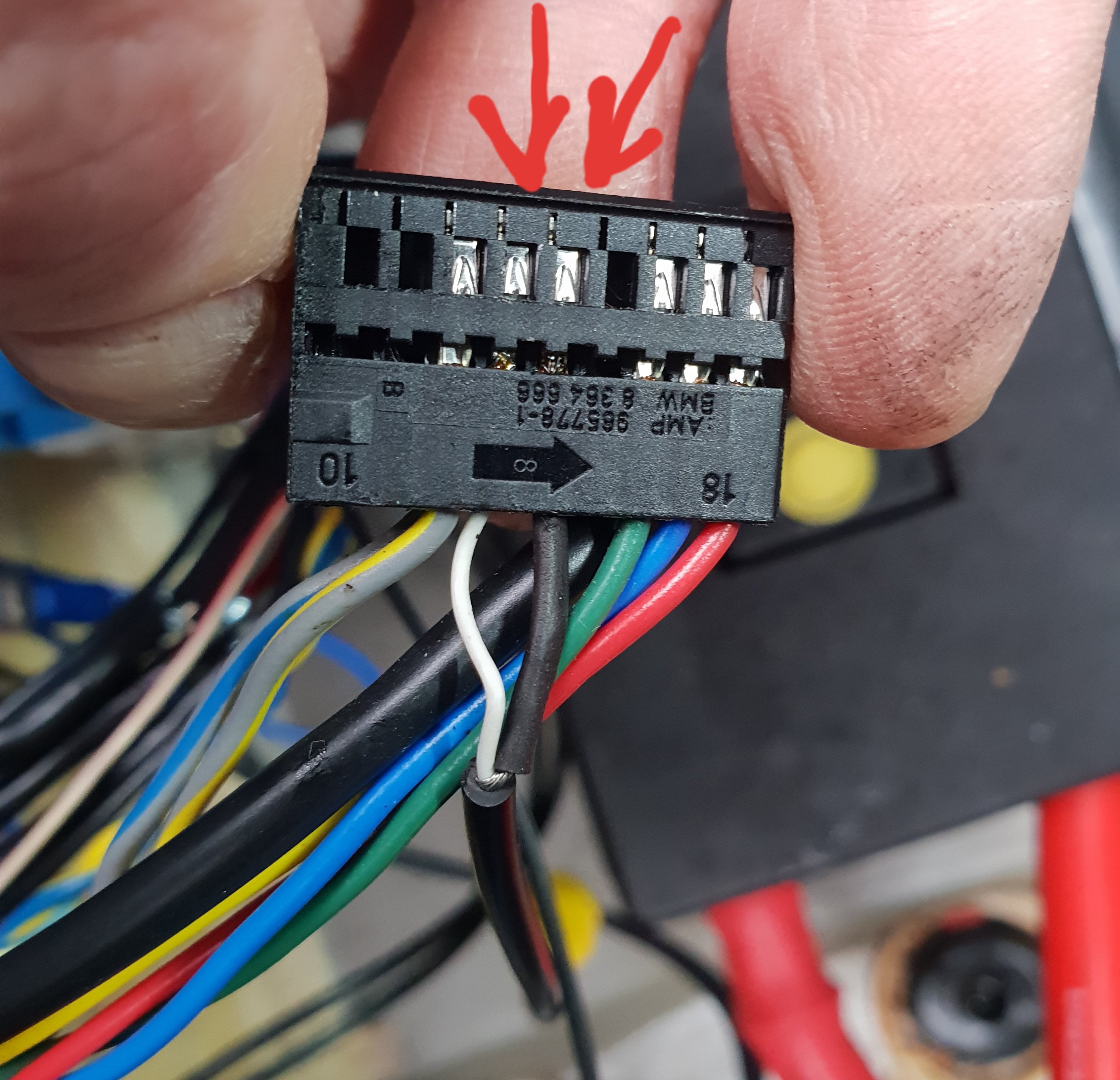
Add the trigger pin into slot 17 in the blue plug and the video pins into slot 13 and 14 of the white plug (13 is the feed, 14 the ground). You will see on the base of each plug how they are numbered. Insert the new pins in the same orientation as the existing pins. Then reassemble. Job done!
Tested and all works. It turned out I did not need to wire in the trigger wire on the video lead – see part 3.
See:-
Fitting a Reversing Camera – Part 1 installing the camera into position
Fitting a Reversing Camera – Part 2 wiring in the camera
Fitting a Reversing Camera – Part 3 wiring and fitting the trigger relay
Fitting a Reversing Camera – Part 4 soldering the additional pins ready to fit
Fitting a Reversing Camera – Part 5 fitting the additional pins into the plugs, test and play!
Fitting a Reversing Camera – Part 6 buy the additional terminal pins and RCA socket on eBay

5 Comments
Comments are closed.